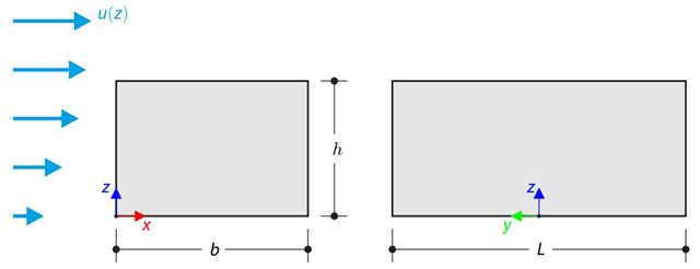
Japoński Instytut Architektury (AIJ) przedstawił kilka dobrze znanych scenariuszy porównawczych symulacji wiatru.
Poniższy artykuł dotyczy "Przypadku E - zespół budynków w rzeczywistym obszarze miejskim o gęstej koncentracji niskiej zabudowy w mieście Niigata".
Poniżej opisany scenariusz jest symulowany w RWIND2, a wyniki są porównywane z symulowanymi i doświadczalnymi wynikami AIJ.
Das Architectural Institute of Japan (AIJ) oferuje analizę porównawczą dla symulacji wiatru.
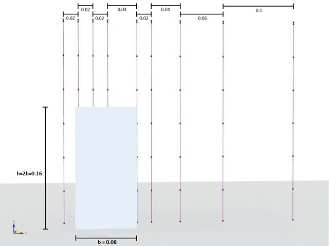
Der Nachfolgende Beitrag dreht sich dabei um den "Przypadek A - wieżowiec w kształcie 2:1:1".
Im Folgenden wird das beschriebene Szenario in RWIND2 unchgebildet und die Ergebnisse mit den den simulierten und der expertellen Resultate des AIJ verglichen.
Japoński Instytut Architektury (AIJ) przedstawił kilka dobrze znanych scenariuszy porównawczych symulacji wiatru.
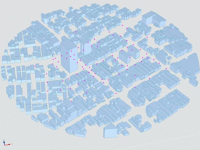
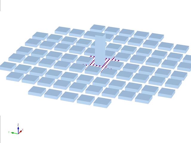
Poniższy artykuł dotyczy "Przypadku D - Wieżowiec wśród bloków miejskich".
Poniżej opisany scenariusz jest symulowany w RWIND2, a wyniki są porównywane z symulowanymi i doświadczalnymi wynikami AIJ.
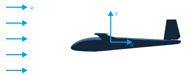
Celem tego przykładu weryfikacyjnego jest analiza przepływu płynu wokół szybowca. Zadanie polega na wyznaczeniu współczynnika oporu powietrza i współczynnika siły nośnej w odniesieniu do kąta natarcia. Współczynniki te można również narysować na wykresie biegunowej oporu. Graniczny kąt dla laminarnego przepływu cieczy wokół profilu skrzydła można również określić na podstawie pola prędkości. Dostępny model 3D CAD (plik STL) jest wykorzystywany w RWIND 2.
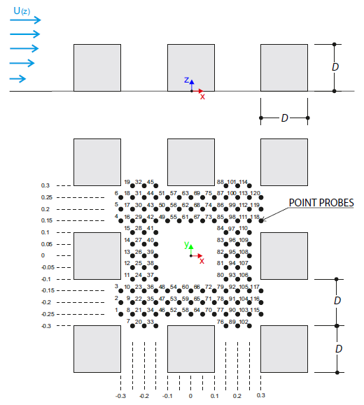
Przykład obliczeniowy opisuje obciążenia wiatrem działające na model grupy budynków w kilku kierunkach. The model consists of eight cubes. The velocity fields obtained by the RWIND simulation are compared with the measured values from the experiment. The experimental data are measured using a thermistor anemometer in the wind tunnel.
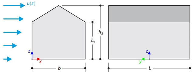
Ten przykład weryfikacyjny porównuje obliczenia obciążenia wiatrem budynku z dachem dwuspadowym, z wykorzystaniem normy ASCE 7-16, z symulacją CFD w RWIND Simulation. The building is defined according to the sketch and the inflow velocity profile taken from the ASCE 7-16 standard.
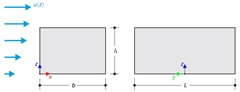
Ten przykład weryfikacyjny porównuje obliczenia obciążenia wiatrem budynku z dachem płaskim, przeprowadzone w normie ASCE 7-16, z wykorzystaniem symulacji CFD w RWIND Simulation. The building is defined according to the sketch and the inflow velocity profile taken from the ASCE 7-16 standard.
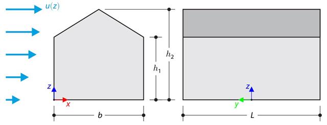
W przykładzie obliczeniowym porównano obliczenia obciążenia wiatrem budynku z dachem dwuspadowym, przeprowadzone zgodnie z normą EN 1991-1-4, z wykorzystaniem symulacji CFD w RWIND Simulation. The building is defined according to the sketch, and the inflow velocity profile is taken according to the standard EN 1991-1-4.
W przykładzie obliczeniowym porównano obliczenia obciążenia wiatrem budynku z płaskim dachem zgodnie z normą EN 1991-1-4 z wykorzystaniem symulacji CFD w RWIND Simulation. The building is defined according to the sketch, and the inflow velocity profile is taken according to the standard EN 1991-1-4.
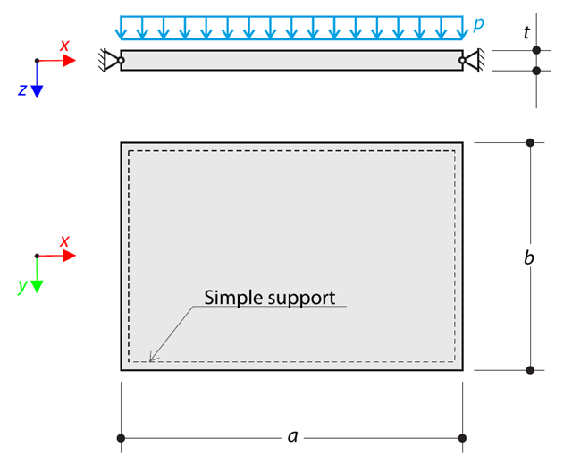
Cienka prostokątna płyta ortotropowa jest swobodnie podpierana i obciążona równomiernie rozłożonym ciśnieniem. The directions of axes x and y coincide with the principal directions. While neglecting self-weight, determine the maximum deflection of the plate.
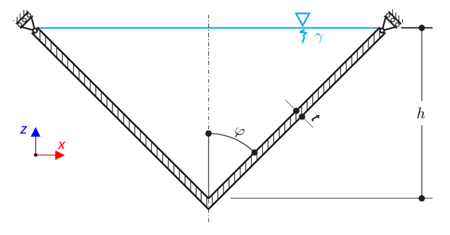
Cienkościenne naczynie stożkowe wypełnione jest wodą. Thus, it is loaded by hydrostatic pressure. While neglecting self-weight, determine the stresses in the surface line and circumferential direction. The analytical solution is based on the theory of thin-walled vessels. This theory was introduced in Verification Example 0084.
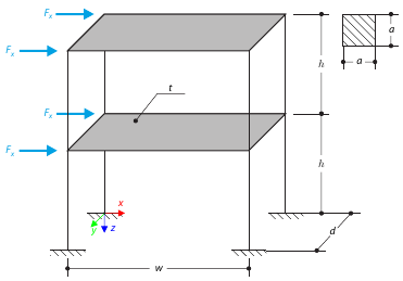
Przykład ten służy do zademonstrowania ograniczenia membrany. The application is shown on a two-story structure. The structure is loaded by means of lateral forces according to Figure 1. Determine the maximum deflection of the structure ux in the direction of the loading forces using both the diaphragm constraint and the plate model of the floor.
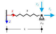
Celem tego przykładu jest pokazanie nieodwracalnego procesu spowodowanego tarciem. After the loading and unloading, the end-point is in a different position than where it was at the beginning. Determine the movement of the node in the X direction.
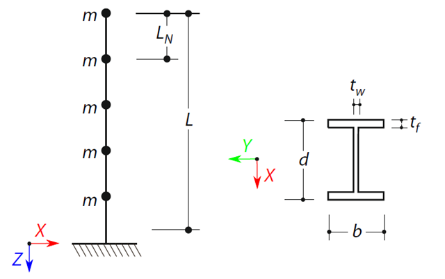
Zostanie zdefiniowana belka wspornikowa o przekroju dwuteowym o długości L. The beam has five mass points with masses m acting in the X-direction. The self-weight is neglected. The frequencies, mode shapes, and equivalent loads of this 5-DOF system are analytically calculated and compared with the results from RSTAB and RFEM.